This page is more "Wikipedia" in nature than the more "tutorial" nature of most of my pages.
This page will be most useful to readers who are already a bit of familiar with the Arduino, or a clone.
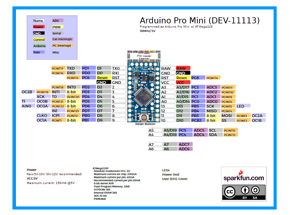
The image above may be a little overwhelming, at first glance... but things really aren't as bad as they seem.
The page will be most useful to Arduino Pro Mini users... but most of what's here applies to other Arduinos. They just have more (or fewer!) of the things explained below. Some may have a few other "special" pins... but not pins you "need" for getting started with Arduinos.
--------------------
The six pins along the right hand edge are for connecting the Arduino to the PC used to program it. Yes, they have other uses, which perhaps we'll come to, but for a beginner, that's all you need to know... other than: Please be sure to plug the connector to the PC onto those pins the right way up!
Many of the pins are for basic input and output. I'll explain "basic I/O" in more detail later.
First the good news: Take out the basic I/O pins, and all you are left with to learn about is the pins shown with green blobs with red centers in the following...
Let's get the "miscellaneous", "odds and ends" pins out of the way first...
By the way... the page may seem "long" and "boring" (not enough pictures!), but don't be alarmed. There's nothing particularly difficult here, but it does take a few words to tour the different pins of the Pro Mini. But until you know what's there, how will you be able to select things that will be useful to you?
Every electrical device needs two connections to a voltage. People often say "connect it to a power supply." (A power supply is for supplying a voltage.)
One of the connections is called "ground", often abbreviated to GND. If you are using a battery to supply your voltage, the "negative" end of the battery is the GND connection.
The Arduino has two pins marked "GND"... and there's another in the six along the right hand edge. (It's the bottom one.)
You connect one of them to the GND side of the power you will be using to run your Arduino. If you plug your Arduino into a PC, to program the Arduino, that will connect the Arduino to the GND side of the voltage it will run on... that voltage will be coming from the PC, through the cable also used to program the Arduino.
Once you have connected that, you have GND available out of the other two GND pins. It is important to have the GND parts of everything in your circuits connected together. (Except in special cases, which involve two separate sources of voltage. Even where we have separate sources of voltage, we will often interconnect the GNDs.)
--------------------
There are two pins marked "Vcc"... and there's another in the six along the right hand edge. (It's the third from the bottom.)
You connect one of them to a reliable source of the positive voltage required by your Arduino. (Some run on 5v, some run on 3.3v, which is often written "3v3"... same thing!) The voltage should be quite stable, and always close to 5 or 3v3. (For the simple, beginner's life. There are things an expert could quibble over that advice.)
Once you have connected that, you have Vcc available out of the other two Vcc pins.
Be careful! You don't want to connect up two sources of voltage at the same time. (They can "fight" with one another in many cases.)
You can use different sources of voltage at different times, though! This might come up as follows:
Suppose you are building a burglar alarm controlled by an Arduino. Some of the time, it will be plugged into the PC which is being used to program the alarm system. While that's the case, the voltage for the Arduino will be supplied though the programming cable, from the PC.
But you don't want to have the big PC on all the time!
In the early days of development, you can unplug the cable (between the PC and the Arduino) from the PC and plug it into any simple USB charger.
But that still leaves your programming cable tied up.
You can also make up a much simpler cable: USB at one end, and a plug to go to the Arduino at the other end. But the only connections this cable will make are the ones for GND and 5v from the USB charger. ((TO BE CHECKED!!.... I'M NOT SURE THIS very simple answer will work if you are using a 3v3 Arduino... ONLY USE IT WITH 5v ARDUINOS until this question is clear
--------------------
The other "misc" pins: There's one marked "RAW".
If you do not have any of the Vcc pins connected to a source of voltage, you can instead connect this to a voltage from a little above the Vcc of your Arduino (3v3 or 5v) up to not more than 12v. This voltage, as long as it doesn't get to close to your Vcc, can "wobble"... it doesn't need to be as precisely controlled as any voltage you feed in via a Vcc pin. If you've done this, a voltage regulator on the Pro Mini will provide Vcc to everywhere it is needed, and to the Vcc pins. Note that if you are using this option, you must not connect circuits which will "draw" very much current. ("Draw" isn't really a very good word for what we are talking about. No circuit "pulls" current... but the lower a circuit's resistance (and/or impedance), the more current will flow into it... until the capability of the source of the voltage in the circuit is overwhelmed... not a good situation to create.)
More "misc" pins: There are two marked "RST", for "reset". (They are directly connected to one another, just like the GND and Vcc pins are.) These are normally left connected to nothing. If either is connected to GND, then when that connection is broken again, the Arduino will do a reset, i.e. behave as it if has lost power and been turned on again. (Pressing the RESET button at the left hand end of the Pro Mini connects the RST pins to ground until it is released.
And, for my fellow obsessives, just to be thorough, there are the pads on the "interior" of the Arduino Pro Mini to which you might want to make connections. (Unlikely in the case of beginners! Those pads are a bit of a nuisance to use, just because of where they are. They "work" perfectly well in any other sense... but don't, for a beginner, have any special powers.))
These are, left to right, A6, A7, A5 and A6. More "ordinary" I/O pins, which we discussed briefly previously, and are just about to discuss in detail. You can use these pins for analog input. As before, with an analog input, you can also use at least some of the pins for digital I/O. For some reason, the reference I am consulting just now only shows A4 and A5 as having alternative "digital use" names, D18/ D19 respectively. I don't know why A6 and A7 aren't shown as, alternatively, D20 and D21. It may just be a "scrap" of the history of the device's development. Perhaps is it okay to set A6 up as a digital output with pinMode(A6,OUTPUT). I don't know! With 17 easily available digital outputs, I haven't yet needed to fuss with "can I use A^ and A& too?" yet! (Not to mention that connecting to these is a pain.)
A simple Arduino has digital I/O pins 0-13. Of these, several are "special"...
----------------
D0 and D1 are used in the serial interface between your Arduino and the PC you are using to program the Arduino. The same channel is used by the system's very useful serial monitor. (If you aren't using that yet, try to learn how!)
Unless you are very short of digital I/O for your needs, it is probably best to leave D0 and D1 out of your plans, so that what you are doing with them and what the system is doing with them don't clash.
----------------
D10-D13 are used to create the SPI bus. You may not know what that is now, but someday you will learn to love it. If you are using a "fancy" shield, for instance one to give your Arduino access to an SD memory card, you are probably using the SPI bus.
If you are using the SPI bus, it is probably best to avoid using D10- D13 for other things at the same time. There are situations of shared use which are okay... but if you don't already know that, you aren't ready to start doing it!
D13 is "special" in another way: In many cases, on the Arduino's PCB, there will be an LED connected to D13 and thence, through an appropriate resistor, to ground. Not only then, is D13 "compromised" by this "extra" hardware, but you should also be aware of the following little "gotcha": As the system boots up, D13 will be made an output. (All the other i/o lines come out of a reset as inputs.) And the system software, before it executes whatever you've put in setup();, will briefly take D13 high before returning it to low.
A0-A5, the analog pins: If you don't happen to need them as analog pins, you can just use them as digital pins! (As the "ordinary" digital I/O pins are used.) Just refer to them as "A0" to "A5", or as pins 14 to 19. Thus, the following would work:
   pinMode(A0,OUTPUT);
   digitalWrite(14,HIGH):
(That would make the "Analog0" pin a digital output, and set it high.)
At a very much more advanced level, I have another page on pin use for you. It focuses on pins used by ethernet interface and SD card carrier shields, but many general issues about pin usage arise.
Fear not! Your adventure mastering the Arduino is not over. There's always what's in the following to master! (Look carefully, and you'll see things you already know... in the labels nearest the pins...
(You can get a better copy of this via the source, at Sparkfun.)
That's A Good Start to mastering the Arduino pins. I have had many years of happy play, based on nothing more than the above. If you have encountered "sticking points" in your attempts to start on an Arduino, suggestions for revisions to the material above are always welcome. Spare the next person the problems you had!
What next? You should learn about the pull up resistors quite soon. Not difficult, and make your life easier! Using PWM isn't hard to master, and is quite useful for some things. The other topics can wait... unless you are determined to do a project that needs the knowledge one of them entails! (Items marked "main site" merely take you to the main Arduino.cc page about the topic. If you want me to write about it, tell me.)
You also need to be (or become!) Very Clear on just what "an input" or "an output" is! This is one of those things which you may think you "understand", but you may find that your understanding will deepen and mature as you continue the journey. Be on the lookout for stuff that will help you achieve these things.
SPI and I2C are "protocols" (an agreed set of rules) used for connecting various "standard" devices. If you understand using either (or both!) of them, a whole bunch of "stuff" becomes "attachable" to your Arduino.
Next topics to master, in no particular order after the top topic...
Ick! The Arduino site calls PWM "analog output", which it isn't, really. But it can seem a bit like analog output, I concede. PWM isn't so hard to understand that it is worth the "dumb down" "analog output" approximation! You want to do something "clever"? You shouldn't be afraid to put in a little "work"!
![]() Page tested for compliance with INDUSTRY (not MS-only) standards, using the free, publicly accessible validator at validator.w3.org
Page tested for compliance with INDUSTRY (not MS-only) standards, using the free, publicly accessible validator at validator.w3.org
CSS behind the page checked, at least once upon a time!, with http://jigsaw.w3.org/css-validator/
Why does this page cause a script to run? Because of the Google panels, and the code for the search button. Also, I have some of my pages' traffic monitored for me by eXTReMe tracker. They offer a free tracker. If you want to try one, check out their site. Why do I mention the script? Be sure you know all you need to about spyware.
....... P a g e . . . E n d s .....